12h/24h Digital Clock Circuit Design Using 7493
The 4 blocks of a digital clock are
- 1 Hz clock generator to generate 1 PPS (pulse per second) signal to the seconds block.
- SECONDS block - contains a divide by 10 circuit followed by a divide by 6 circuit. Will generate a 1 PPM (pulse per minute) signal to the minutes block. The BCD outputs connect to the BCD to Seven Segment circuit to display the seconds values.
- MINUTES block - identical to the seconds block it contains 2 dividers; a divide by 10 followed by a divide by 6. Will generate a 1 PPH (pulse per hour) signal to the HOURS block. The BCD outputs connects to the BCD to Seven Segment circuit to display the minutes values.
- HOURS block - depending on whether it is a 12 or 24H clock, will have a divide 24 or divide by 12. For 24H, it will count from 00 to 23. For 12H, it will count from 00 to 11. The BCD outputs connects to the BCD to Seven Segment circuit to display the hours values.
SECONDS block
The 74LS93 is used to implement the divide by 10 and divide by 6 circuits. The 74LS93 is a high-speed 4-bit ripple type counters partitioned into two sections. The counter has a divide-by-two section and divide-by-eight section which are triggered by a HIGH-to-LOW transition on the clock inputs.
Please go to truncated ripple counter to learn how the 74LS93 works.
Divide by 10 Counter
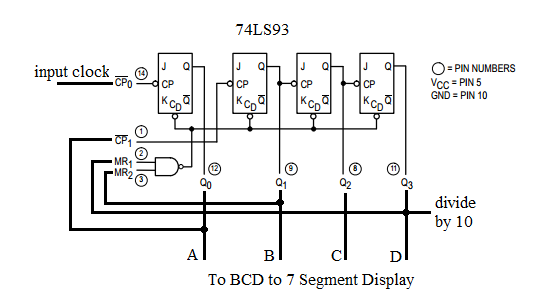
- In order to use all 4 bits of the counter, Q0 must be connected to CP1. Q0 is LSB and Q3 is MSB.
- The input clock is connected to CP0.
- To implement a divide by 10 or MOD10 counter, Q1 is connected to MR1 and Q3 is connected to MR2. With this connection, when the count reaches 10 (1010 binary), it resets to 0.
- The output frequency at Q3 is the input clock frequency divided by 10.
- To display the values, Q3..Q0 are connected to the respective D..A inputs of the BCD to 7 segment display.
Divide by 6 Counter
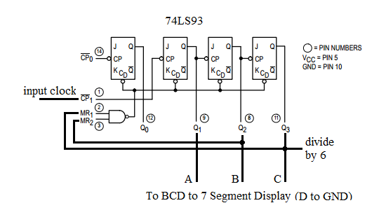
- Since only 3 bits are required Q0 is not used. Q1 is LSB and Q3 is MSB.
- The input clock is connected to CP1.
- To implement a divide by 6 or MOD6 counter, Q2 is connected to MR1 and Q3 is connected to MR2. With this connection, when the count reaches 6 (110 binary), it resets to 0.
- The output frequency at Q3 is the input clock frequency divided by 6.
- To display the values, Q3..Q1 are connected to the respective C..A inputs of the BCD to 7 segment display. D of the BCD to 7 segment display input is connected to GND.
HOURS block
The clock can be designed as a 24H or 12H clock. We will explain the steps to arrive at the combinational logic to obtain a 12H clock and we will leave it to the reader to design the 24H clock as an exercise. Click hints if you need help to design the 24H clock.
12H Clock
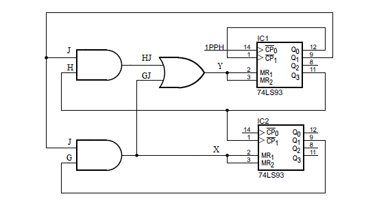
- In order to use all 4 bits of the IC1 (ones) counter, Q0 must be connected to CP1. Q0 is LSB and Q3 is MSB. The input clock is connected to CP0.
- Since less than 3 bits are required for IC2 (tens), Q0 is not used. Q1 is LSB and Q3 is MSB. The input clock is
connected to CP1.
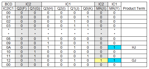
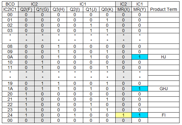
- The truth table of the counter is abbreviated - omitting those rows where the MR inputs to the counters are 0. Recall that for the 7493, a 1 to the MR will reset the counters to 0.
- To simplify the table, K is Q0 of IC1 (ones), G is Q0 of IC2 (tens) and so on.
- For the 12H clock, when the count in BCD reaches
- 0A, IC1 must be cleared (Y=1)
- 12, IC1 must be cleared (Y=1) and IC2 must be cleared (X=1)
- Using SOP (sum of products), we obtain
- Y = HJ + GJ where Y is the IC1 MR1, MR2 inputs connected together
- X = GJ where X is the IC2 MR1, MR2 inputs connected together
Simulate and Breadboard the 24H Clock circuit.
1 Hz Clock
The 1 Hz clock can be implemented using the schmitt trigger oscillator.
Limitations
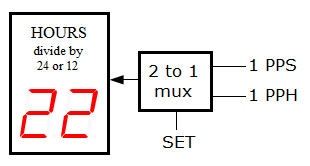
- The clock cannot be set to the correct time. Hint - use additional logic to allow the 1 PPS clock to drive the
MINUTES and HOURS block depending on a button press. Below is the block diagram of one solution using a 2 to 1 multiplexer. Depending on SET, either the 1 PPS (Pulse Per
Second) or the 1 PPH (Pulse Per Hour) clock drives the Hour circuit.
- The 12H clock counts from 00 to 11 rather than 01 to 12. Hint - use regular JK flip flops (74LS73) instead of the 74LS93 so on terminal count, the counter output is preset to 01.