Stepper Motor Circuit
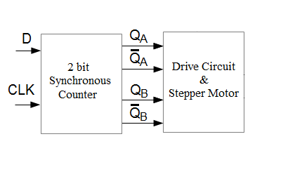
The following schematic shows the different blocks in a circuit to drive a unipolar stepper motor. The 2 blocks are
- 2 bit synchronous counter - Inputs are D (direction) and CLK. D will determine the direction of rotation and the CLK frequency will set the rotation speed.
- Motor Driver circuit and Unipolar Stepper Motor - the Motor Driver circuit translate the QA and QB digital signals to appropriate drive currents required by the stepper motor.
2 bit synchronous counter
The following state diagram describes the stepper motor sequence.
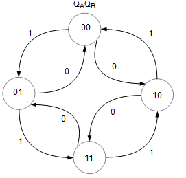
It is obtained from the table below. With the state diagram, go to synchronous circuit design to derive the schematic.
Motor Driver circuit and Unipolar Stepper Motor
A common stepper motor is the four-coil unipolar. They are called unipolar because they require only that their coils be driven on and off.

The stepper motor shown is the PF443-03A from Mycom. It is specified at a supply voltage of 12V and the coil current is 0.31A. Each step is 1.8 degrees. For prototyping purpose, you may supply the stepper motor from 5V.
The stepper motor cannot be driven directly from the output of the flip flops. The ULN2003, a high voltage, high current darlington driver comprising seven NPN darlington pairs, is used to drive the motor. All feature integral clamp diodes for switching inductive loads. The ULN2003 has a maximum sustaining output voltage of 50V and maximum output current of 0.5A per channel which easily meet the requirements of the Mycom PF443 stepper motor.
The stepping sequence for a four-coil unipolar steppers is shown. If you run the stepping sequence forward, the stepper rotates clockwise; run it backward, and the stepper rotates counterclockwise. The motor’s speed depends on how fast the controller runs through the step sequence.