Ring Counter
A ring counter is a Shift Register (a cascade connection of flip-flops) with the output of the last flip flop connected to the input of the first. It is initialised such that only one of the flip flop output is 1 while the remander is 0. The 1 bit is circulated so the state repeats every n clock cycles if n flip-flops are used. The "MOD" or "MODULUS" of a counter is the number of unique states. The MOD of the n flip flop ring counter is n.
It can be implemented using D-type flip-flops (or JK-type flip-flops).
RESET must be 1!
-
Notes:
- Enable the flip-flops by clicking the RESET (Green) switch. The RESET switch is a on/off switch (similar to a room light switch)
- Click on CLK (Red) switch and observe the changes in the outputs of the flip flops. The CLK switch is a momentary switch (similar to a door bell switch - normally off).
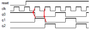
- The D flip-flop clock has a rising edge CLK input. For example Q1
behaves as follows:
- The D input value just before the CLK rising edge is noted (Q0).
- When CLK rising edge occurs, Q1 is assigned the previously noted D value (Q0).
- The MOD or number of unique states of this 3 flip flop ring counter is 3.
- Simulate and Breadboard the Ring Counter circuit.
| Truth Table | |||
|---|---|---|---|
| State | Q0 | Q1 | Q2 |
| 0 | 1 | 0 | 0 |
| 1 | 0 | 1 | 0 |
| 2 | 0 | 0 | 1 |